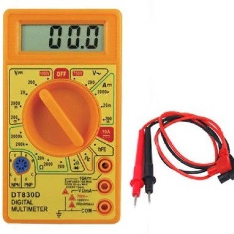
Versatile and Reliable Digital Multimeter for Precise Measurements
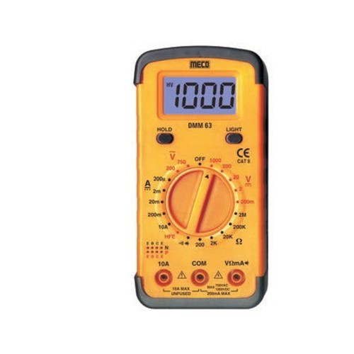
Our Meco 63 digital multimeter is a powerful tool for measuring various electrical parameters. With its 3 ½ digit LCD display and multiple measurement functions, this multimeter is ideal for electronics, DIY projects, and industrial applications.
Key Features:
- Accurate Measurements: Measures AC/DC voltage, AC/DC current, resistance, and more with precision.
- 3 ½ Digit LCD Display: Easy-to-read display for clear readings.
- Data Hold Function: Holds readings for easy viewing and recording.
- Diode and Transistor Testing: Test the functionality of diodes and transistors.
- Audible Continuity Test: Quickly identify continuity in circuits.
- Backlit Display: Provides clear visibility in low-light conditions.
- Compact and Portable: Lightweight and portable design for easy use.
- Battery-Powered: Convenient operation with a single 9V battery.
Applications:
- Electronics: Troubleshoot and repair electronic circuits.
- DIY Projects: Test components and measure electrical parameters.
- Industrial Maintenance: Diagnose and maintain electrical equipment.
- Automotive: Test electrical systems in vehicles.
- Laboratory: Conduct electrical experiments and measurements.
Specifications:
- Display: 3 ½ digit LCD display
- Maximum Reading: 1999 counts
- Power Source: One 9V battery
- Battery Life: Approximately 200 hours
- Operating Temperature: 0°C to +50°C
- Storage Temperature: -20°C to +60°C
Order now and experience the precision and versatility of our M-eco 63 digital multimeter!
DATA SHEET AND USECASE
Key Features:
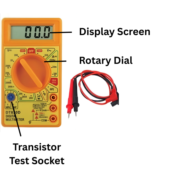
- Display: 3½-digit LCD (1999 count) for clear readings.
- Measurements:
- DC Voltage: Ranges of 200mV, 2V, 20V, 200V, and 1000V.
- AC Voltage: Ranges of 200V and 750V.
- DC Current: Ranges of 200µA, 2mA, 20mA, 200mA, and 10A.
- Resistance: Ranges of 200Ω, 2kΩ, 20kΩ, 200kΩ, and 2000kΩ.
- Additional Functions:
- Diode Testing: Measures forward voltage drop.
- Transistor Testing: Provides hFE (DC gain) measurements.
- Continuity Test: Audible buzzer for circuit continuity checks.
- Signal Generator: Outputs a square wave signal.
- Protection: Overload protection and low battery indication.
Usage Instructions:
-
Preparation:
- Ensure the multimeter is powered by a 9V battery.
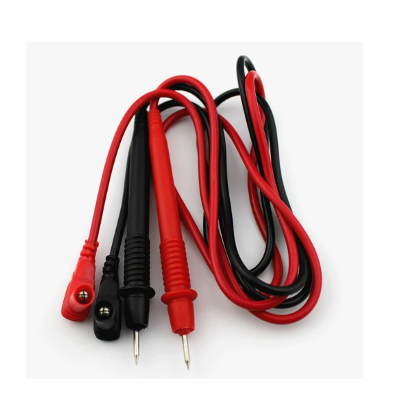
- Inspect test leads for any damage before use.
-
Measuring Voltage (DC/AC):
- Turn the rotary switch to the appropriate DCV or ACV range.
- Connect the black test lead to the "COM" jack and the red test lead to the "VΩmA" jack.
- Place the probes across the component or circuit under test.
- Read the voltage value displayed.
-
Measuring Current (DC):
- Turn the rotary switch to the appropriate DCA range.
- For currents up to 200mA, use the "VΩmA" jack; for currents up to 10A, use the "10A" jack.
- Connect the black test lead to the "COM" jack and the red test lead to the appropriate current jack.
- Break the circuit and connect the multimeter in series with the load.
- Read the current value displayed.
-
Measuring Resistance:
- Turn the rotary switch to the appropriate resistance (Ω) range.
- Connect the black test lead to the "COM" jack and the red test lead to the "VΩmA" jack.
- Ensure the circuit is de-energized before measuring.
- Place the probes across the resistor or component.
- Read the resistance value displayed.
-
Diode and Continuity Testing:
- Turn the rotary switch to the diode/continuity test position.
- Connect the test leads to the diode or circuit.
- For diodes, read the forward voltage drop; for continuity, listen for the buzzer indicating a closed circuit.
-
Transistor Testing:
- Set the rotary switch to the hFE position.
- Insert the transistor's leads into the appropriate NPN or PNP sockets.
- Read the hFE value displayed.